Main Menu
A field ground fault can occur when insulation damage creates an electrically conductive path from anywhere on the field winding (or elsewhere on the excitation circuit) to the rotor forging. In this diagram, we represent those faults as resistors. If two faults occur at different locations along the winding, excitation current is diverted through the forging, and severe burning of both insulation and rotor steel can occur rather quickly.
In figure 1, we represent those faults as resistors. As insulation on the field windings degrades, resistance (RL) drops toward 0, and a fault occurs.
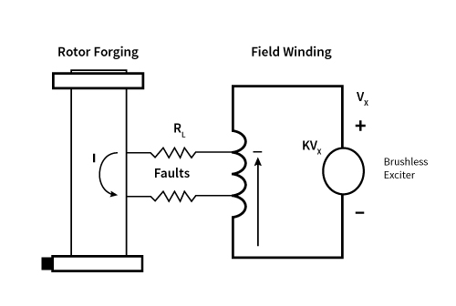
Figure 1 - Field Ground Fault on a Generator or Motor with Brushless Exciter. Resistors (RL) can become fault locations as resistance drops
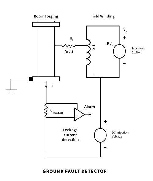
Figure 2 - Classical DC Voltage Injection Method
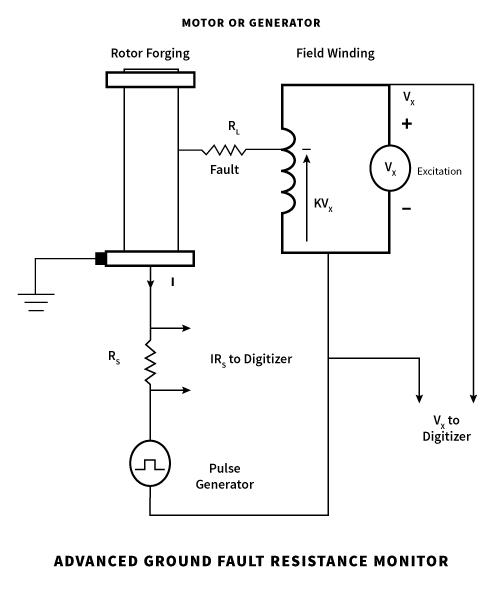
Figure 3 - Advanced Pulse Injection Method
Most field ground detectors in service today use the classical DC Voltage Injection Method (figure 2). Notice the excitation circuit with an exciter that supplies current to the field winding. When a ground fault occurs, it is represented by a resistance (RL) from some location on the winding to the rotor ground. The voltage potential at the fault location relative to the negative field terminal is K*VX, where K is called the location factor, and VX is the excitation voltage. K takes a value between 0 and 1 for locations between the negative terminal and the positive terminal. The ground detector circuit makes a connection between the rotor ground and the excitation circuit, usually on the negative terminal as shown here. A small DC voltage is injected across this connection, and the current flow through the circuit is measured. If a ground fault, RL, occurs, a current will flow through the ground detector circuit. When that current exceeds a fixed current threshold, a ground fault alarm is triggered. The injection voltage insures that some current will flow when a ground fault occurs, even if the fault occurs at the negative excitation terminal. Faults occurring closer to the positive terminal along the field winding will occur at higher fault resistance. In other words, the severity of fault that will cause an alarm is dependent on the fault location.
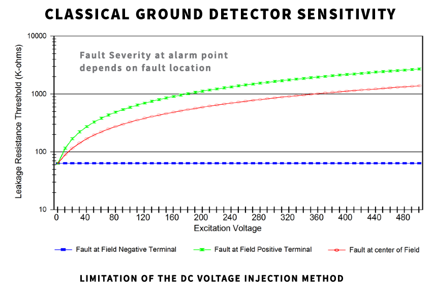
The above plot demonstrates a limitation of classical detection methods. The three curves on this plot show the sensitivity at the alarm point: for a fault at the negative terminal in blue, the midpoint of the field in red, and the positive terminal in green. You see that for a field voltage of around 300 volts, the severity of the fault at the alarm point will vary by more than an order of magnitude.
Unlike the classical ground fault detection technique, advanced ground fault detection using the Pulse Injection Method (figure 3) can determine the severity and location of the fault. This method is similar to the classical method in that the measurement involves making a connection between the negative excitation terminal and rotor ground and measures the current flowing through that connection. Rather than just a DC injection voltage, a low frequency pulse is injected into the circuit. Instead of just alarming when a current threshold is exceeded, advanced systems continually measure the current flow with a high precision. The pulsing action provides two steady state current levels. This method provides the system enough data to solve two simultaneous equations to calculate values for the two unknown variables: the insulation resistance, RL, and the location factor, K. Operators use this data to determine the true severity and approximate location of the fault, allowing them to make the best decisions about how and when to repair or replace the motor or generator.