Main Menu
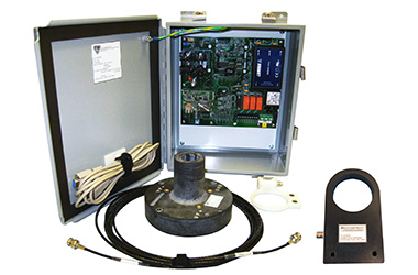
Combining advanced innovations in measurements with digital telemetry for brushless synchronous generators/motors, the Accumetrics Rotor Health Monitor Model AT-8300 provides predictive maintenance trending data for temperature measurements and rotor field ground fault resistance for condition based monitoring (CBM).
The Rotor Health Monitor AT-8300 can monitor up to 12, 3-wire RTDs (PT100 style), with readings updated every 10 seconds. Up to 24 of 2-wire RTD’s can alternatively be measured (contact Accumetrics at time of order). If a current shunt is installed at the field negative potential, then the system can measure field current. Using the ratio of the field voltage to the field current, a calculated average copper temperature is then provided (shunt not included).
By using 16-bit digital rotor telemetry technology, the Rotor Health Monitor AT-8300 allows users to monitor fault resistance trends over time and track the progression of ground faults from their onset. This provides the possibility of early warning of impending failure and allows for predictive maintenance. Two adjustable-threshold 4-20 mA alarm relay contacts and digital data output of all measured parameters are provided, allowing warning, shutdown, and predictive maintenance tracking for ground faults.
AT-8300
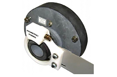
Transmitter, Antenna, and Receiver
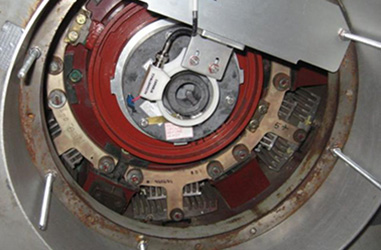
AT-8300 Rotor Health Monitor Installed
| SPECIFICATIONS | |
|---|---|
| Performance | |
| RTD Measurements | |
| General Information | PT100 RTDs (installed by user), Up to 12 RTD 3-wire sensors (Also available: 24 of 2-wire RTDs), Approximate 10 second duration to read all RTDs |
| Measurement range | -58 to 572 ºF (50 to +300 ºC) |
| Accuracy | ±1.5 ºC |
| Average Field Winding Temperature | Calculated from directly measured field voltage divided by directly measured field current |
| Field Voltage | |
| Measurement range | 0 to 500 VDC (Contact factory for other ranges) |
| Maximum Transient without Damage | 1000 V for 5 seconds |
| Field Current Measurement Range | Measured by a low level differential voltage from a customer supplied 0-100 mV current shunt installed at the negative terminal so that common mode voltage is within ± 0.75 V of Vf Negative connection. Two redundant channels are provided. |
| Ground Fault Resistance Measurement | |
| Measurement Range | 0 to 80 MΩ |
| Accuracy | ± 250 Ω ± 2% of reading 0 to 500 kΩ (exclusive of AC content and noise effects from the excitation system) |
| Ground Fault Location Factor | |
| Range | 0 to 100%, representing the ratio of the potential at the ground fault to that of the total field voltage (0% if the fault is at negative terminal; 100% at positive terminal) |
| Accuracy | ± 1% for a 10 kΩ fault and field excitation ≥ 25 V |
| Receiver Alarm Outputs | |
| Outputs | Two independent relay alarm contacts with user programmable configurations and thresholds. Alarm 1 is always ground fault resistance threshold. Alarm 2 is user selectable for either ground fault resistance threshold or for average field winding temperature. |
| Malfunction | Active upon detection of a malfunction in monitor operation or loss of receiver power |
| Alarm Interfaces | Form C relay: 6 A, 250 VAC |
| Receiver Analog Outputs Standard Outputs | Two channels of 4-20 mA current loop, configurable for scale and parameter. Parameters: Earth Fault Resistance (log scale), Field V, Shunt Field I, Field Resistance, Field Average Temperature, Shunt mV |
| Receiver Digital Interface | |
| Computer Interfaces | RS232, Ethernet interfacing to PC based RHM Console Software; full documentation provided for user-developed software |
| Output Data | CSV data and Ethernet streamed readings of ground fault resistance, RTD readings, field voltage and currents, field winding resistance and resultant winding temperature, ground fault location factor, alarm status. |
| User Settings | Earth Fault Alarm Resistance Thresholds, Alarm Dwell Time, Field Current Settings, Analog output 1 and 2 configuration, Alarm 2 threshold settings (Earth fault or Field Temp), Network Settings, Archive setup. |
| RHM Console Software Features | Control of User Settings (see above) Fault resistance trend graph; numeric display of fault resistance & location, field voltage, currents, resistance & average winding temperature; RTD temperatures; system status. Archival data storage in .csv files for importing into MS Excel. |
| Physical | |
| Rotor Connections | Field positive and negative terminals, rotor ground, RTD inputs, and connections to current shunts (located at the field negative terminal) |
| Transmitter Mounting Information | End of shaft mounted transmitter, approximately 150 mm diameter, contact Accumetrics for special adapters or other mounting requirements. |
| Environment | |
| Ambient Temperature | 32 to 185 ºF / 0 to 85 ºC at rotor transmitter, 32 to 122 ºF / 0 to 50 ºC maximum at receiver |
| Rotor Speed | 4320 RPM max (3600 RPM with up to 20% overspeed) |
| Receiver Power | 85 to 250 VAC 50 / 60 Hz, <20 W |
| Receiver Ambient Temperature | 32 to 122 ºF / 0 to 50 ºC; thermoelectric cooling is available as an option |